
The parts
How the lights carry power and data, the twist-lock connector on every part, and which wire goes where.
How the lights work
Every strand carries three conductors: 24 V power, ground and data. The controller box plugs into an AC outlet like a lamp, and everything downstream of it is 24 VDC.
Data travels one direction only: from the controller to the first puck, which relays it down the line. So:
- Every strand has a male end, where data comes in, and a female end, where data goes out.
- Male ends always point toward the controller, and a strand has no way of being connected backwards.
- Each puck drops the voltage slightly. After 75 pucks you need power injection — see section 6.
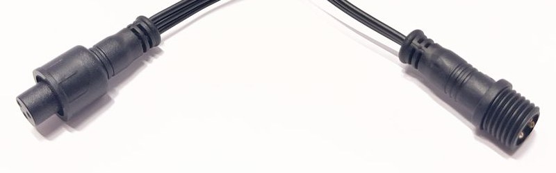
The connector (mini-X twist-lock)
Left: the female end, with its locking nut. Right: the threaded male end — the smaller of the two. Every light and every wire has one of each.
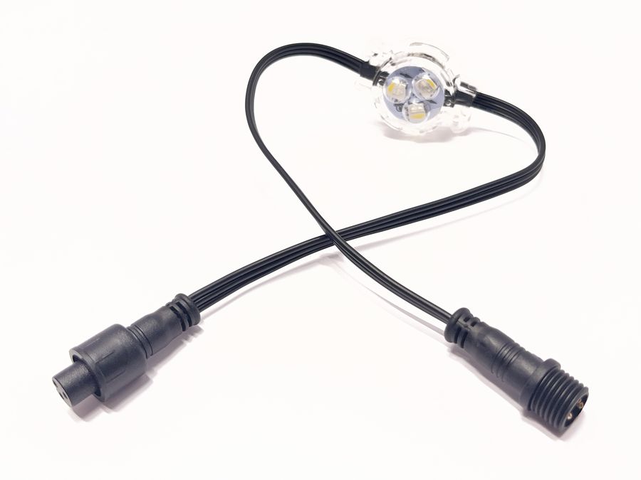
A single light: a connector on each end. Strings of five, every length of wire and the power-injection tees are the same.
One connector, on everything
There’s one kind of connection, made at the factory. Line up the pins, push the two ends together and turn the nut until it’s snug. That joint is sealed against rain, sprinklers and humidity.
Male ends always point toward the controller box. On every light, wire and tee. There’s only one way to put a run together.
What you never do on site
- Strip, cut or splice wire
- Solder anything
- Crimp a terminal or a butt connector
- Heat-shrink a joint
- Use lever clips or wire nuts outdoors — they aren’t rated for wet locations
What you do instead
- Drill a 5/8″ hole wherever a wire enters the run
- Push the cable’s small male end up through it with a fish rod
- Run it back through the attic to the controller in the garage
- Twist everything together, male toward the controller
- At the very end of a run — no more lights — twist the waterproof plug into the last light’s female end
Cut the track, never the wire. If a full track won’t fit at the end of a run, cut it and fill with single pucks. Bridge gaps (gable, downspout, garage) with 3′ flat wire or a 25′ section. A cut connector can’t be replaced on site.
Four wires, connectors on both ends
Nothing comes on a spool. Every wire is a fixed length with connectors on both ends — you choose a length, never cut one.
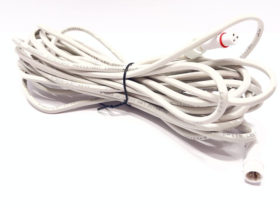
25′3-conductor, Class 2
24 V, ground and data, from the start of a run back to a controller channel. Attic-rated.
25′2-conductor, Class 2
24 V and ground only, for power injection: from a tee’s 2-pin end back to a controller power output. Attic-rated.
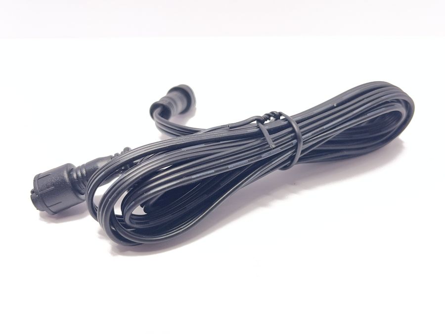
3′Flat 3-conductor
24 V, ground and data, for short jumps outside — corners, downspouts, gaps. Lies flat in the track.
3′Flat 2-conductor
24 V and ground only, for short power jumps outside.
Up to four 25′ sections
Twist 25′ sections together to reach the controller — up to four, never more than 100 ft. Shorter runs are more reliable, so take the most direct path.
Stay away from AC power lines
In the attic, keep Chameleon wire away from the house’s AC wiring; it can interfere with the data line.
The DIY kit includes four of each.